Voyager 1: One Light Day
If you’ve ever had the opportunity to escape civilization and look up at our impressive night sky, you’ll know how easy it is to feel insignificant compared to the endless stars scattered across the expansive view. It seems to serve as a harsh reminder that our human existence and farthest reach will forever be limited to an infinitesimally small percentage of our universe.
But through human ingenuity, a stubborn curiosity, and pure grit, two probes launched nearly 50 years ago speed through interstellar space toward the outer reaches of our solar system as they push that human reach ever further. On Wednesday, November 18, 2026, at 10:16:07 UTC, Voyager 1, the farthest man-made object from our planet, will have traveled a full light-day from its humble beginnings at Launch Complex 41 (LC-41) in Cape Canaveral, Florida.
When the Planets Aligned
The Voyager missions would first be conceived in the mind of Gary Arnold Flandro, while he was researching planetary trajectories for JPL. In 1964 he realized that a rare planetary alignment would be experienced from around 1976 to 1980, offering an unprecedented opportunity for scientific research upon planets some of which we had only prior gotten blurry atmosphere-distorted glimpses of.
| Mission | Launch | Now | From Sun | Speed |
|---|---|---|---|---|
| Jupiter–Pluto | SEP 8, 1977 | LEAVING PLUTO | 39.4 AU | 23.1 KM/S |
| Jupiter–Saturn | OCT 11, 1978 | LEAVING SATURN | 18.3 AU | 22.0 KM/S |
| Jupiter–Uranus | OCT 11, 1978 | LEAVING URANUS | 27.6 AU | 21.0 KM/S |
| Jupiter–Neptune | NOV 12, 1979 | LEAVING NEPTUNE | 40.2 AU | 23.9 KM/S |
| Grand tour | OCT 7, 1978 | LEAVING NEPTUNE | 40.1 AU | 26.1 KM/S |
Missions after G. A. Flandro, Astronautica Acta 12 (1966), recomputed as patched conics. Planets: JPL Horizons.
This once in nearly two decade synergy was dependent on being able to accurately calculate a trajectory across multiple planet-assisted gravity boosts, in this case up to four. Flandro’s true genius and discovery lay in his realization that using gravitational boosts of planets could actually allow you to perform the full tour in a shorter amount of time. Using bleeding edge computational calculations he was able to perform a brute force search and discover the trajectories he presented in his paper.
His work ignited a flurry of excitement in the scientific community, eventually resulting in a detailed 85 report advising NASA to seize the once in 175 year chance to expand human-kinds knowledge of the universe. The proposal suggested four separate probes, with one flying the original Grand Tour proposed by Flandro, and another veering off to visit Pluto. The program also called for a brand new spacecraft architecture called TOPS (Thermoelectric Outer Planets Spacecraft), designed to be extremely redundant and support the plethora of disparate requirements for scientific instruments.
After Fig. 51, Thermoelectric Outer Planets Spacecraft (TOPS), JPL TM 33-589, 1973 (NASA/JPL-Caltech).
After Fig. 40, Thermoelectric Outer Planets Spacecraft (TOPS), JPL TM 33-589, 1973 (NASA/JPL-Caltech).
After Fig. 8, Thermoelectric Outer Planets Spacecraft (TOPS), JPL TM 33-589, 1973 (NASA/JPL-Caltech).
After Fig. 41, Thermoelectric Outer Planets Spacecraft (TOPS), JPL TM 33-589, 1973 (NASA/JPL-Caltech).
The ambitions of the Grand Tour as proposed would prove to be perhaps too grand. With shrinking budgets in the post-Apollo era and the looming price tag of the newly approved Shuttle program, NASA and the White House saw no room for a 1bn expedition to the outer reaches. The project was canceled before it could even reach congress for approval, and NASA focused efforts on the shuttle program and other ongoing projects.
Drawn after NASA Lewis Research Center, TM X-68249 (1973) and TM X-71692 (1975).
Scientists, researchers and even engineers are not known for letting go of once-in-a-lifetime opportunities, and the members of JPL are no different. The program would be rebuilt from the ground up with a focus on scaling it back, instead of a new architecture engineers looked to the proven technology of previous NASA programs. The primary computer systems, alignment sensors, and digital tape recorder would come from the Viking program which was aiming for a pair of Mars landings in the mid 70s. The primary bus, scan platform, telecommunications and launch vehicle would be modeled after Mariner and Pioneer programs.
Model after JPL drawings and NASA/JPL-Caltech's 3D model. Labels after JPL Voyager Mission Status Bulletin No. 13, 1978.
Even with all the adjustments there wasn’t room for the full scope of the original plan, so it was further scaled back to just two probes, and two planet visits. Now a much more digestible project with a lifespan of four years and a budget of only 250$m, the restructure worked and the program now named “Mariner Jupiter-Saturn 1977” or “MJS77” would be approved by congress in May 1972.
After the MJS77 trajectory selection, Figure 1 (NASA/JPL-Caltech).
The aforementioned stubbornness of JPLs staff was still ever-present however, while the program was presented as purely a two planet plan, they had managed to leave the option for the original Grand Tour open. Voyager 1 being sent on a shorter and faster trajectory, would let it reach Jupiter and Saturn months before its sibling. It would take the opportunity to dive close past Saturn’s moon Titan, collecting crucial science data on its pass, but sacrificing the required momentum for reaching Uranus and Neptune.
This sacrifice was seen as well worth it by scientists as Titan was deemed to present the greatest mystery among the moons in our solar system. Having been discovered to contain methane gas in its atmosphere, but being occluded by dense haze making it impossible to even size up, it offered a tantalizing opportunity to learn more about what scientists expected to be a time capsule resembling early earth.
After JPL Voyager Mission Status Bulletin No. 1, 1977 (NASA/JPL-Caltech). Scan: The Planetary Society.
If Voyager 1 had failed in its mission, Voyager 2 would have taken its place performing the same pass and also falling short of the required momentum for further planet encounters. But the hope was in the footsteps of Voyager 1’s success, the second probe could instead use Saturn as another gravitational slingshot letting it reach and study both Uranus and Neptune, thus completing the original vision of the Grand Tour.
Launch
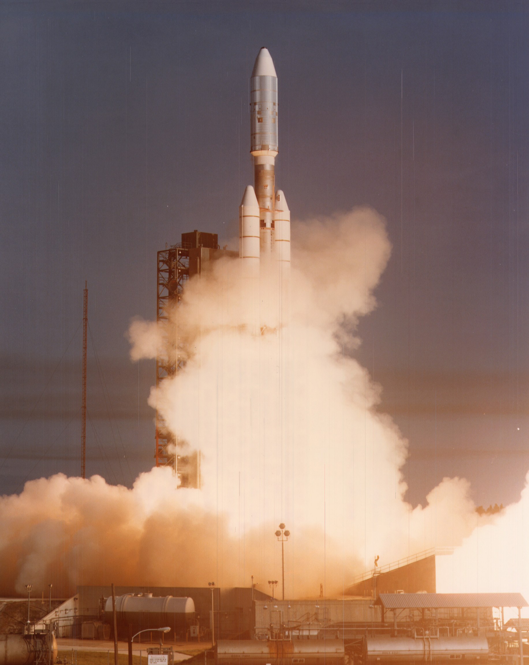
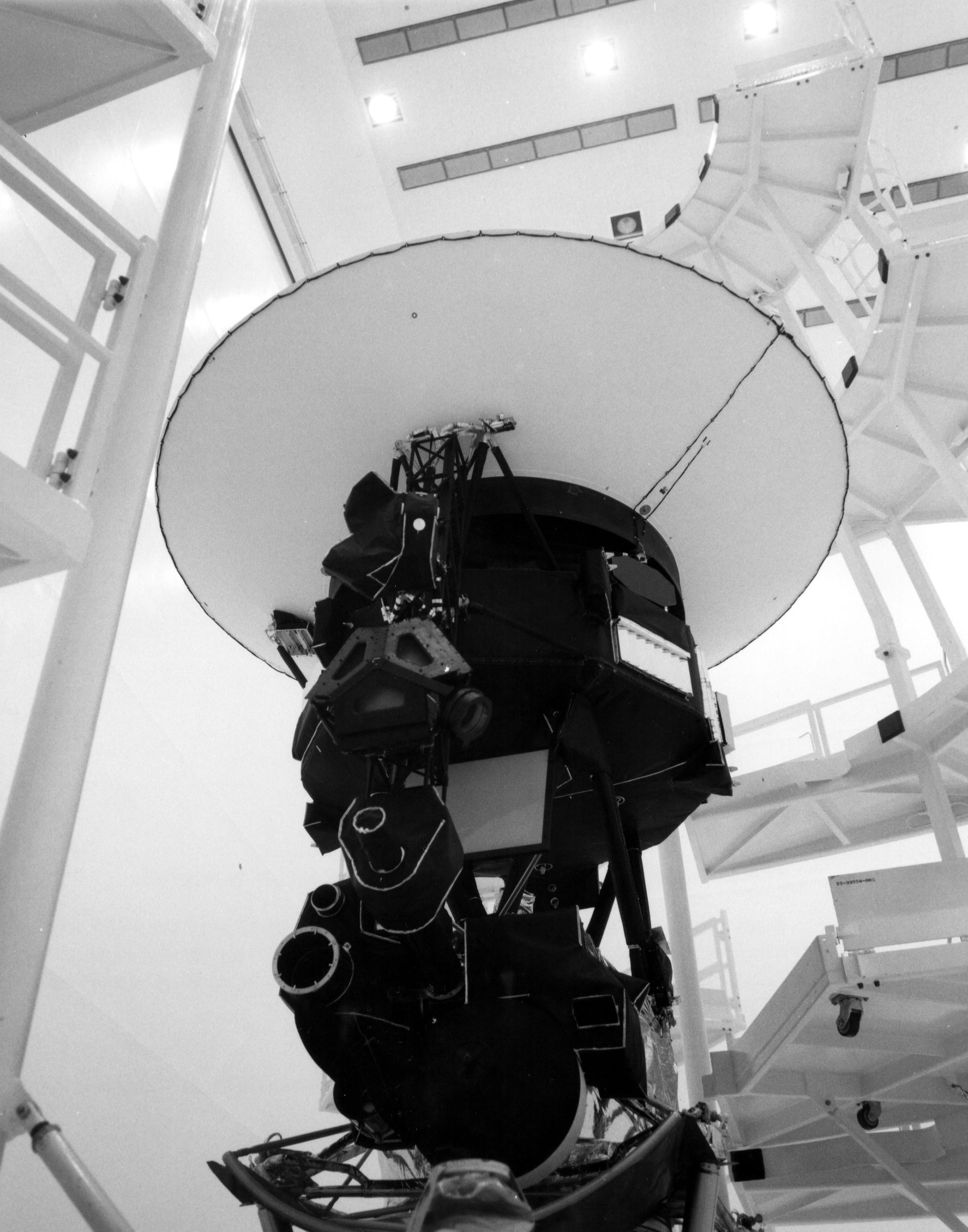
Voyager 1 was launched on September 5, 1977 just 16 days after its sibling Voyager 2 (this seeming affront to consistent naming will make sense later). It’s troubles would begin only 8 minutes after its departure.
Simulated from the TC-6 Voyager Flight Data Report (NASA Lewis Research Center) and the Titan IIIE/Centaur D-1T Systems Summary (Convair and Martin Marietta, 1973), fitted to the report's measured gaps at staging. Not flight telemetry.
The Titan IIIE Stage II which was meant to burn for 210s cut off 2.26 seconds short when an oxidizer flow-rate anomaly tripped a premature propellant-depletion cutoff. Without the added thrust, Voyager 1 seemed doom to miss its trajectory.
However in a demonstration of the launch platforms robustness, the Centaur D-1T upper stage, whose guidance system detected the velocity and altitude deficit, extended its burn by 3.4s to compensate. The few dozen kilograms of extra fuel and oxidizer allowing this came courtesy of a punctual departure, minimizing the reserve propellant lost to cryogenic boil-off while waiting on the pad or and circumventing the need for any trajectory adjustments due to a launch later in the window.
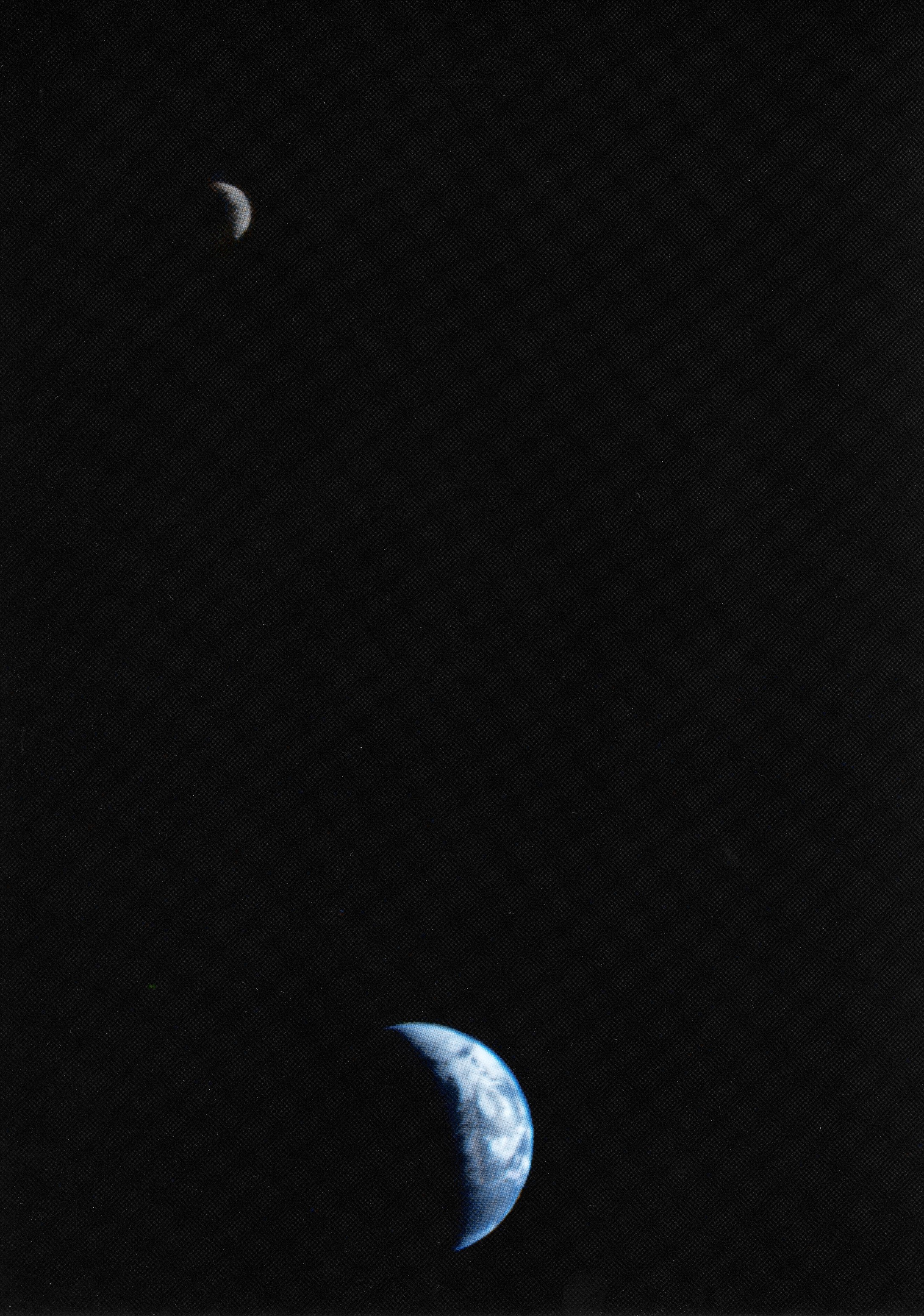
13 days later Voyager 1 would take the first single-frame image of the Earth and Moon, from a distance of 7.25 million miles. While not part of the original plan, a failure on Voyager 2’s scan-platform boom to fully lock into place required engineers to perform further diagnostics before it would be ready. This same failure would cause engineers to push back the second probes launch twice, both times for work to ensure a repeat of the issue wouldn’t occur. And indeed these changes proved successful as the second probes checkout was completed without issue, and it earned the opportunity to snap the now famous picture.
Frozen in Gear
While it was able to dodge the same boom-locking issues of Voyager 2, it wasn’t so lucky weeks later during a routine calibration slew on the same two-axis scan platform. This time the actuators designed to smoothly move and aim the platform suddenly slowed, seizing in azimuth and raising fears the platform may lock up entirely before reaching Jupiter.
Scan Platform
Model after JPL drawings of the scan platform; labels after its Figure 5-4.
The scan platform is a stabilized extension of the probe for mounting scientific instruments that required “aiming” at targets, like the planets Voyager passed by at high speed. Having a separate platform that could move freely was critical as the spacecrafts core design was dependent on aiming its massive transmitters and receivers directly at earth.
Model after JPL drawings and NASA/JPL-Caltech's 3D model; spacecraft axes after JPL Voyager Mission Status Bulletin No. 16, 1978.
But pointing an object hurdling through space at 50,000mph hour preceisly towards an invisible spec billions of miles away is no easy feat. Making it even more difficult Voyager had no IMU (Inertial Measurement Unit), only a IRU (Inertial Reference Unit) that would be turned on and used briefly during high-rate maneuvers. Instead the probes had to rely on the same premise that has led us to learning about them, looking at the stars. By correlating the position of the sun with one of two stars (normally Canopus, Vega as a redundant option) the probe can accurately point towards earth, and stabilize its orientation.
FROM VOYAGER 15 SEP 1978
Imaging Science System (ISS)
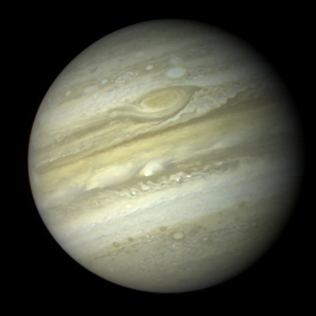
Of the 10 primary scientific instruments located aboard Voyager, 4 of those could be found on the articulated scan platform. Perhaps most obviously the Imaging Science System a twin set of slow-scan vidicon television cameras, one narrow-angle (1500mm) for high-resolution surface/cloud details and one wide-angle (200mm) for broader context and color mapping.
Three frames together · 3 February 1979
Frames as read out
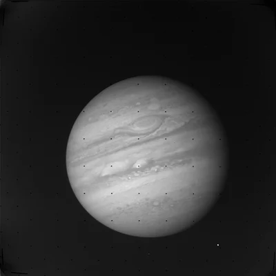 Orange
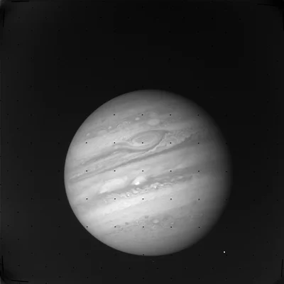 Green
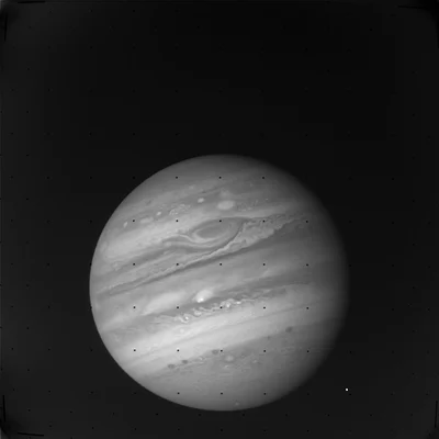 Blue
Frames: Voyager 1 ISS narrow-angle camera, C1548448, C1548450 and C1548452 (NASA PDS Ring-Moon Systems Node, VGISS_5105). Camera after Smith et al. 1977, Space Science Reviews 21, 103–127.
Infrared Interferometer Spectrometer and Radiometer (IRIS)
The Infrared Interferometer Spectrometer and Radiometer (IRIS) was used for measuring thermal energy radiated by planets and moons to better determine their atmospheric temperatures, vertical pressure profiles, and even chemical compositions.
- Time into scan
- 45.6 s
- Mirror travel
- 1.57 mm
- Path difference
- +2.33 mm
- Detail resolved
- 4.3 cm−1
- Wavenumber
- 731 cm−1
- Wavelength
- 13.7 µm
- Its ripple in the signal
- every 0.20 s
- As bright as a black body at
- 139 K
- Emission from
- Acetylene
Data: Voyager 1 IRIS calibrated spectra of Titan, 11–12 November 1980 (Hanel, Conrath et al.; NASA PDS VG1/VG2-S-IRIS-3-RDR-V1.0). Instrument simplified from its optical layout in Hanel 1981 (NASA TM-82156).
Ultraviolet Spectrometer (UVS)
The Ultraviolet Spectrometer (UVS) analyzed ultraviolet light absorbed or emitted by the atmospheres of planets to identify upper-atmosphere composition, auroras, and interstellar hydrogen glow.
Photopolarimeter Subsystem (PPS)
And finally the Photopolarimeter Subsystem (PPS) was a 0.2-meter telescope with various color filters and polarizers that could be used to measure atmospheric aerosols, surface textures, and ring particle size.
Deep Space Network
Drag to turn
Accurate alignment on Voyager’s side was only one half of the problem, to pickup the faint signals on earth requires massive dishes. Luckily for NASA work decades earlier had already been done to build the Deep Space Network, a geodistributed array of huge satellite dishes designed to pick up the weakest signals from the farthest reaches of space.
Solution
Engineers used the identical Proof Test Model in a vacuum chamber to diagnose the issue, down to tiny debris caught in the actuator gear train, enough to cause problems with its tight tolerances.
[TODO: expand this, visuals]
Jupiter
March 5, 1979 (Jupiter Closest Approach): Radiation Single-Event Upsets & The Io Plume Discovery
Saturn
The Titan Gamble
The Death of the PLS Cup
Late November 1980 (Post-Saturn Departure): The Death of the Plasma Science (PLS) Cup
Pale Blue Dot
February 14, 1990 (40 AU Out): The “Pale Blue Dot” & Wiping the Onboard Computers
Living On
“We didn’t design them to last 30 years or 40 years, we designed them not to fail.”
November 2017 & November 2023 (13+ Billion Miles Out): The 37-Year-Dormant Thruster Swap & The 22.5-Hour Code Patch
One of my first questions when diving into my research around Voyager 1, was simply “how”. I have a significant history with software development, and building massive scale, highly redundant systems. Still the thought of building either the hardware or software responsible for persisting on through 4, even 8 years of intense space flight is horrifying. Between the immense forces experienced at launch, the constant barrage of solar rays, or the intense magnetic forces (nearly 20,000 times that on earth) experienced at Jupiter, it’s perhaps the most gruelling environment you could imagine for a digital computer-controlling a hodge podge of analog instruments.
The answer has revealed itself over the bread of research I’ve done, and I think it just comes down to every single team responsible for working on the Voyager program exceeding their goals and expectations by an impressive margin. This margin has allowed both the original team and the plethora of successors to limp these impressive space probes along, allowing them to continue discovery decades after anyone would have thought possible.
Of Voyager 1s 10 original scientific instruments, 4 are still functioning and providing new data for scientists and researchers on earth. Most of the others have simply been turned off due to power constraints, further showing the impressive redundancy and resiliency of the numerous distinct systems and instruments.
Power
RADIOISOTOPE
THERMOELECTRIC
GENERATOR
- 470 W
- POWER AT LAUNCH
- Pu-238
- FUEL
Model after JPL drawings and NASA/JPL-Caltech's 3D model.
Conserving power raises one of next most interesting questions, how do you power a spacecraft of any type for over 50 years? The answer comes in one of the most reliable forms of “power” we know, radiological decay. Harnessing the heat from a chunk of Plutonium-238, the radioisotope thermoelectric generator (RTG) uses the Seebeck effect to at provide 470W of power at launch. That same decay puts a realistic cap to the lifespan of the mission, regardless of how redundant everything else is the power continues to drop consistently over time, and sometime after 2030 will simply be too low to maintain core systems.
Lorem ipsum
Ut enim ad minima veniam, quis nostrum exercitationem ullam corporis suscipit laboriosam, nisi ut aliquid ex ea commodi consequatur? Quis autem vel eum iure reprehenderit qui in ea voluptate velit esse quam nihil molestiae consequatur, vel illum qui dolorem eum fugiat quo voluptas nulla pariatur?
At vero eos et accusamus et iusto odio dignissimos ducimus qui blanditiis praesentium voluptatum deleniti atque corrupti quos dolores et quas molestias excepturi sint occaecati cupiditate non provident, similique sunt in culpa qui officia deserunt mollitia animi, id est laborum et dolorum fuga.
Et harum quidem rerum facilis est et expedita distinctio. Nam libero tempore, cum soluta nobis est eligendi optio cumque nihil impedit quo minus id quod maxime placeat facere possimus, omnis voluptas assumenda est, omnis dolor repellendus.
Temporibus autem quibusdam et aut officiis debitis aut rerum necessitatibus saepe eveniet ut et voluptates repudiandae sint et molestiae non recusandae. Itaque earum rerum hic tenetur a sapiente delectus, ut aut reiciendis voluptatibus maiores alias consequatur aut perferendis doloribus asperiores repellat.
Dolor sit amet
Lorem ipsum dolor sit amet, consectetur adipiscing elit. Vivamus lacinia odio vitae vestibulum vestibulum. Cras venenatis euismod malesuada. Nullam ac erat ante. Integer nec odio praesent libero, sed cursus ante dapibus diam. Sed nisi nulla quis sem at nibh elementum imperdiet.
Duis sagittis ipsum praesent mauris. Fusce nec tellus sed augue semper porta. Mauris massa vestibulum lacinia arcu eget nulla. Class aptent taciti sociosqu ad litora torquent per conubia nostra, per inceptos himenaeos. Curabitur sodales ligula in libero.
After JPL Voyager Mission Status Bulletin No. 13, 1978 (NASA/JPL-Caltech). Scan: The Planetary Society.
Sed dignissim lacinia nunc. Curabitur tortor. Pellentesque nibh. Aenean quam. In scelerisque sem at dolor. Maecenas mattis. Sed convallis tristique sem. Proin ut ligula vel nunc egestas porttitor. Morbi lectus risus, iaculis vel, suscipit quis, luctus non, massa.
Fusce ac turpis quis ligula lacinia aliquet. Mauris ipsum. Nulla metus metus, ullamcorper vel, tincidunt sed, euismod in, nibh. Quisque volutpat condimentum velit. Class aptent taciti sociosqu ad litora torquent per conubia nostra, per inceptos himenaeos.
Nam nec ante. Sed lacinia, urna non tincidunt mattis, tortor neque adipiscing diam, a cursus ipsum ante quis turpis. Nulla facilisi. Ut fringilla. Suspendisse potenti. Nunc feugiat mi a tellus consequat imperdiet. Vestibulum sapien. Proin quam. Etiam ultrices.
- Date
- FEB 14, 1990
- Voyager 1 · from Sun · above plane
- 40.4 AU · +32.8°
- Voyager 2 · from Sun · above plane
- 31.4 AU · −1.3°
Trajectories: JPL Horizons.
- Source
- Voyager 1 · 1980
- Surface pressure
- 1.5 bar
- Surface temperature
- 94 K
- Main gas
- N₂
Predictions: Pollack 1973; Danielson et al. 1973; Caldwell 1978; Hunten 1978; Tyler & Eshleman 1978; Martin Marietta 1979; radii Cruikshank 1978. Measured: Lindal et al. 1983; Fulchignoni et al. 2005; JPL.
- Received at Earth
- 07:12:30
- Spacecraft time
- 05:47:43
- From Titan's centre
- 10,057 km
- Ray's lowest altitude
- 11 km
- Latitude probed
- 7.6° N
Trajectory: JPL Horizons. Ray bending computed from Lindal et al. 1983.
- Received at Madrid
- 07:10:58.0
- Frequency shift
- −11.0 Hz
- S-band strength
- 100%
- X-band strength
- 100%
Data: Voyager 1 radio science, Titan occultation, DSS-63 open-loop recordings (Tyler et al.; NASA PDS VG1-SSA-RSS-1-ROCC-V1.0).
- Altitude
- 0 km
- Voyager 1 · 1980
- 94.0 K
- Huygens · 2005
- 93.5 K
- Pressure
- 1,495 mbar
- Number density
- 1.19 × 1020 cm−3
Data: Lindal et al. 1983, Icarus 53, 348–363; Huygens HASI, Fulchignoni et al. 2005 (both via NASA PDS Atmospheres Node).
Phase boundaries: NIST Chemistry WebBook; IAPWS; Setzmann & Wagner 1991. Earth: US Standard Atmosphere 1976. Titan: Lindal et al. 1983.
Consectetur adipiscing
Suspendisse in justo eu magna luctus suscipit. Sed lectus. Integer euismod lacus luctus magna. Quisque cursus, metus vitae pharetra auctor, sem massa mattis sem, at interdum magna augue eget diam. Vestibulum ante ipsum primis in faucibus orci luctus et ultrices posuere cubilia curae.
Morbi lacinia molestie dui. Praesent blandit dolor. Sed non quam. In vel mi sit amet augue congue elementum. Morbi in ipsum sit amet pede facilisis laoreet. Donec lacus nunc, viverra nec, blandit vel, egestas et, augue. Vestibulum tincidunt malesuada tellus.
Ut ultrices ultrices enim. Curabitur sit amet mauris. Morbi in dui quis est pulvinar ullamcorper. Nulla facilisi. Integer lacinia sollicitudin massa. Cras metus. Sed aliquet risus a tortor. Integer id quam. Morbi mi. Quisque nisl felis, venenatis tristique, dignissim in, ultrices sit amet, augue.
Proin sodales libero eget ante. Nulla quam. Aenean laoreet. Vestibulum nisi lectus, commodo ac, facilisis ac, ultricies eu, pede. Ut orci risus, accumsan porttitor, cursus quis, aliquet eget, justo. Sed pretium blandit orci.
Sed do eiusmod
Ut eu diam at pede suscipit sodales. Aenean lectus elit, fermentum non, convallis id, sagittis at, neque. Nullam mauris orci, aliquet et, iaculis et, viverra vitae, ligula. Nulla ut felis in purus aliquam imperdiet. Maecenas aliquet mollis lectus.
Vivamus consectetuer risus et tortor. Lorem ipsum dolor sit amet, consectetur adipiscing elit. Integer nec odio. Praesent libero. Sed cursus ante dapibus diam. Sed nisi. Nulla quis sem at nibh elementum imperdiet. Duis sagittis ipsum. Praesent mauris.
V
V V V V V V V V V V V V V V V V V V V V V V V V V V V V V V V V V V V V V V V V V V V V V V V V V V V V V V V V V V V V V V V V V V V V V V
V V V V V V V V V V V V V V V V V V V V V V V V V V V V V V V V V V V V V V V V V V V V V V V V V V V V V V V V V V V V V V V V V V V V V V
V
V V V V V V V V V V V V V V V V V V V V V V V V V V V V V V V V V V V V V V V V V V V V V V V V V V V V V V V V V V V V V V V V V V V V V V
V V V V V V V V V V V V V V V V V V V V V V V V V V V V V V V V V V V V V V V V V V V V V V V V V V V V V V V V V V V V V V V V V V V V V V
V
V V V V V V V V V V V V V V V V V V V V V V V V V V V V V V V V V V V V V V V V V V V V V V V V V V V V V V V V V V V V V V V V V V V V V V
V V V V V V V V V V V V V V V V V V V V V V V V V V V V V V V V V V V V V V V V V V V V V V V V V V V V V V V V V V V V V V V V V V V V V V
V
V V V V V V V V V V V V V V V V V V V V V V V V V V V V V V V V V V V V V V V V V V V V V V V V V V V V V V V V V V V V V V V V V V V V V V
V V V V V V V V V V V V V V V V V V V V V V V V V V V V V V V V V V V V V V V V V V V V V V V V V V V V V V V V V V V V V V V V V V V V V V
And on, And on, And so forth…
It’s very likely that Voyager 1 will outlive all of us, quietly carrying its message to other lifeforms or perhaps future generations. For the current generation, it serves as a message of determination, persistence, and our ability as humans to yearn for and reach out to the distant corners of our solar system, and universe.
FROM VOYAGER 115 NOV 2026